


Thực hành thiết kế
Thiết kế hệ thống chất lỏng thường được phát triển để đáp ứng các yêu cầu của các hệ thống khác. Ví dụ, trong các ứng dụng làm mát, nhu cầu truyền nhiệt quyết định số lượng bộ trao đổi nhiệt cần thiết, kích thước của chúng và lưu lượng cần thiết. Sau đó, các thông số hiệu suất của bơm được tính toán dựa trên bố cục hệ thống và đặc tính thiết bị. Trong các ứng dụng khác như xả nước thải đô thị, công suất bơm phụ thuộc vào lượng nước cần thiết, cũng như cột áp và áp suất cần thiết. Việc lựa chọn và cấu hình bơm phải được xác định theo yêu cầu về lưu lượng và áp suất của hệ thống hoặc dịch vụ.
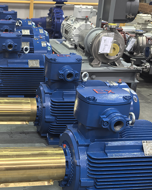
Sau khi xác định các yêu cầu vận hành của hệ thống bơm, cần phải thiết kế tổ hợp bơm/động cơ, bố trí và thông số kỹ thuật van. Việc lựa chọn loại bơm phù hợp, cùng với đặc tính tốc độ và công suất của nó, đòi hỏi phải hiểu rõ nguyên lý hoạt động của nó.
Khó khăn nhất trong quá trình thiết kế là đạt được sự cân bằng hiệu quả về chi phí giữa đặc tính của bơm và động cơ với yêu cầu của hệ thống. Do sự biến đổi đáng kể về lưu lượng và áp suất, việc cân bằng này thường trở nên phức tạp. Để đảm bảo thiết bị đáp ứng yêu cầu của hệ thống trong điều kiện vận hành khắc nghiệt, các nhà thiết kế thường sử dụng thiết kế dự phòng. Hơn nữa, bơm vượt quá thông số kỹ thuật yêu cầu sẽ làm tăng chi phí vật liệu, lắp đặt và vận hành. Tuy nhiên, việc sử dụng hệ thống đường ống có đường kính lớn hơn có thể làm giảm chi phí năng lượng bơm.
Năng lượng chất lỏng
Trong các ứng dụng thực tế của máy bơm, năng lượng chất lỏng thường được đo bằng cột áp (Head). Được đo bằng feet hoặc mét, cột áp đề cập đến chiều cao của cột chất lỏng trong một hệ thống có năng lượng tiềm năng tương đương. Thuật ngữ này rất tiện lợi vì nó kết hợp các yếu tố mật độ và áp suất, cho phép đánh giá máy bơm ly tâm trong các hệ thống chất lỏng khác nhau. Ví dụ, ở một lưu lượng nhất định, máy bơm ly tâm có thể tạo ra các áp suất đầu ra khác nhau đối với các chất lỏng có mật độ khác nhau, nhưng giá trị cột áp trong hai điều kiện này vẫn giống nhau.
Tổng cột áp của một hệ thống chất lỏng bao gồm ba thành phần hoặc phép đo: cột áp tĩnh (áp suất đo), cột áp chiều cao (hay thế năng) và cột áp vận tốc (hay động năng).
Áp suất tĩnh: Như tên gọi cho thấy, nó đề cập đến áp suất của chất lỏng trong một hệ thống, được đo bằng các đồng hồ đo áp suất thông thường. Mặc dù chiều cao mực chất lỏng ảnh hưởng đáng kể đến áp suất tĩnh, nó cũng đóng vai trò là thước đo độc lập về năng lượng của chất lỏng. Ví dụ, một đồng hồ đo áp suất trên một bể thông gió có thể hiển thị các chỉ số áp suất khí quyển. Tuy nhiên, nếu bể được đặt cách máy bơm 15 mét, thì máy bơm phải tạo ra cột áp ít nhất 15 mét để tạo áp suất đẩy nước vào bể.
Cột áp (hay thế năng): Thế năng trọng trường của chất lỏng, được định nghĩa là sự chênh lệch độ cao thẳng đứng giữa đầu vào và đầu ra, đo bằng mét (m). Nó biểu thị khoảng cách thẳng đứng mà chất lỏng được nâng lên.
Áp suất động (còn gọi là "áp suất động") đo năng lượng động học của chất lỏng. Trong hầu hết các hệ thống, nó thường nhỏ hơn áp suất tĩnh. Khi lắp đặt đồng hồ đo áp suất, thiết kế hệ thống hoặc diễn giải các chỉ số đo, cần tính đến áp suất động—đặc biệt là trong các đường ống có đường kính thay đổi. Chỉ số đo ở phía hạ lưu có thể thấp hơn chỉ số ở phía thượng lưu, ngay cả khi khoảng cách giữa chúng chỉ là 0,2 mét.
Tính chất chất lỏng
Ngoài loại hệ thống được phục vụ, nhu cầu về máy bơm còn bị ảnh hưởng bởi các đặc tính của chất lỏng như độ nhớt, mật độ, hàm lượng hạt và áp suất hơi.
Độ nhớt là một thuộc tính đo lường sức cản cắt của chất lỏng. Chất lỏng có độ nhớt cao cần nhiều năng lượng hơn trong quá trình chảy vì sức cản cắt của chúng tạo ra nhiệt. Một số chất lỏng (chẳng hạn như dầu bôi trơn lạnh dưới 15°C) có độ nhớt cao đến mức bơm ly tâm không thể vận chuyển chúng một cách hiệu quả. Do đó, sự thay đổi độ nhớt của chất lỏng trong phạm vi nhiệt độ hoạt động của hệ thống là yếu tố quan trọng trong thiết kế hệ thống. Một tổ hợp bơm/động cơ được thiết kế phù hợp với nhiệt độ dầu 26°C có thể hoạt động yếu hơn khi vận hành ở 15°C.
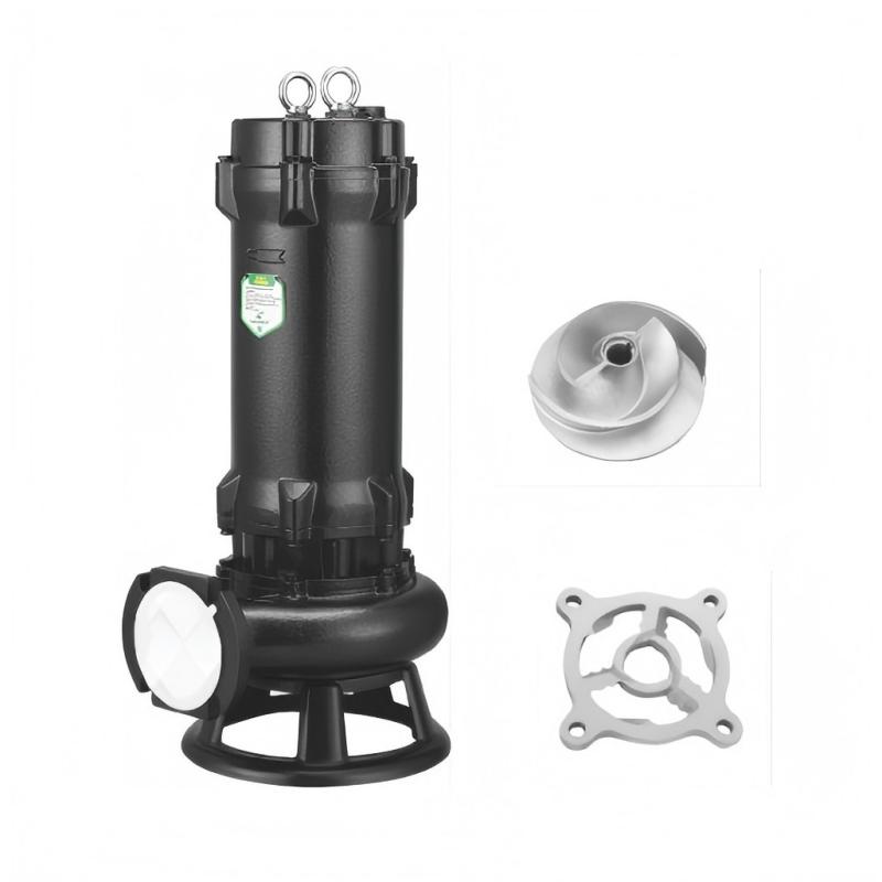
Số lượng và đặc tính của các hạt vật chất trong hệ thống chất lỏng ảnh hưởng đáng kể đến thiết kế và lựa chọn bơm. Một số loại bơm không thể chịu được lượng tạp chất quá mức. Hơn nữa, nếu các vòng đệm giữa các tầng trong bơm ly tâm nhiều tầng bị ăn mòn, hiệu suất của chúng sẽ giảm sút rõ rệt. Các loại bơm khác được thiết kế đặc biệt để xử lý chất lỏng có hàm lượng hạt vật chất cao. Do nguyên lý hoạt động của chúng, bơm ly tâm thường được sử dụng để vận chuyển chất lỏng chứa nhiều hạt vật chất, chẳng hạn như bùn than.
Sự khác biệt giữa áp suất hơi của chất lỏng và áp suất hệ thống là một yếu tố cơ bản khác trong thiết kế và lựa chọn bơm. Việc tăng tốc chất lỏng lên tốc độ cao (đặc điểm của bơm ly tâm) gây ra sự giảm áp suất tĩnh. Sự giảm áp suất này có thể làm giảm áp suất chất lỏng xuống bằng hoặc thấp hơn áp suất hơi của nó. Tại thời điểm này, chất lỏng "sôi" và chuyển từ trạng thái lỏng sang trạng thái khí. Hiện tượng này, được gọi là xâm thực, ảnh hưởng nghiêm trọng đến hiệu suất của bơm. Trong quá trình xâm thực, các bong bóng siêu nhỏ hình thành khi chất lỏng trải qua quá trình chuyển pha. Vì hơi chiếm thể tích lớn hơn đáng kể so với chất lỏng, nên các bong bóng này làm giảm lưu lượng chảy qua bơm.
Hiện tượng phá hoại do xâm thực xảy ra khi các bọt khí này vỡ vụn mạnh và tái nhập vào pha lỏng. Trong quá trình vỡ vụn, dòng nước tốc độ cao tác động lên các bề mặt xung quanh. Lực tác động này thường vượt quá độ bền cơ học của bề mặt bị tác động, dẫn đến sự hao hụt vật liệu. Theo thời gian, xâm thực có thể gây ra các vấn đề ăn mòn nghiêm trọng trong máy bơm, van và đường ống.
Các nguyên nhân khác gây ra hư hỏng tương tự bao gồm dòng chảy ngược hút và dòng chảy ngược xả. Dòng chảy ngược hút đề cập đến sự hình thành các mô hình dòng chảy phá hoại trong vùng hút của cánh quạt, dẫn đến hư hỏng giống như hiện tượng xâm thực. Tương tự, dòng chảy ngược xả xảy ra khi các mô hình dòng chảy phá hoại phát triển ở vùng bên ngoài của cánh quạt. Những hiệu ứng dòng chảy ngược này thường do máy bơm hoạt động ở lưu lượng quá thấp. Để ngăn ngừa hư hỏng như vậy, nhiều máy bơm được ghi nhãn với lưu lượng tối thiểu.
Loại hệ thống
Giống như máy bơm, đặc điểm và yêu cầu của hệ thống bơm rất đa dạng, nhưng nhìn chung có thể được chia thành hệ thống tuần hoàn kín và hệ thống tuần hoàn hở.
Hệ thống tuần hoàn kín: Chất lỏng lưu thông dọc theo một đường dẫn có điểm bắt đầu và điểm kết thúc chung. Các máy bơm phục vụ hệ thống tuần hoàn kín (ví dụ: hệ thống nước làm mát) thường không cần phải vượt qua tải trọng cột áp tĩnh trừ khi có các bể chứa thông hơi ở các độ cao khác nhau trong hệ thống. Trong hệ thống tuần hoàn kín, tổn thất do ma sát từ đường ống và thiết bị của hệ thống tạo thành tải trọng chính đối với máy bơm.
Hệ thống vòng hở: Các hệ thống này có các cổng đầu vào và đầu ra, nơi chất lỏng được vận chuyển từ điểm này đến điểm khác. Không giống như hệ thống vòng kín, chúng thường yêu cầu máy bơm để khắc phục nhu cầu cột áp tĩnh do chênh lệch độ cao và nhu cầu điều áp trong bể chứa. Một ví dụ điển hình là hệ thống thoát nước mỏ, sử dụng máy bơm để bơm nước từ dưới lòng đất lên bề mặt. Trong những trường hợp như vậy, cột áp tĩnh thường là tải trọng chính đối với máy bơm.
Nguyên lý điều khiển dòng chảy
Kiểm soát lưu lượng là yếu tố then chốt đối với hiệu suất hệ thống. Lưu lượng đầy đủ đảm bảo làm mát thiết bị đúng cách và cho phép làm rỗng hoặc nạp đầy bể chứa nhanh chóng. Việc duy trì áp suất và lưu lượng đủ để đáp ứng yêu cầu hệ thống thường dẫn đến việc lựa chọn bơm và động cơ truyền động có công suất lớn hơn mức cần thiết. Vì thiết kế hệ thống tích hợp các thiết bị kiểm soát lưu lượng để điều chỉnh nhiệt độ và ngăn ngừa quá áp thiết bị, việc lựa chọn bơm có công suất lớn hơn mức cần thiết sẽ gây tiêu hao năng lượng cao cho các cơ chế kiểm soát lưu lượng này.
Có bốn phương pháp chính để điều khiển lưu lượng của hệ thống điều khiển hoặc nhánh của nó: van tiết lưu, van bypass, điều khiển tốc độ bơm và kết hợp nhiều bơm. Phương pháp điều khiển lưu lượng phù hợp phụ thuộc vào kích thước và bố cục hệ thống, đặc tính chất lỏng, hình dạng đường cong công suất bơm, tải trọng hệ thống và độ nhạy của hệ thống đối với sự thay đổi lưu lượng.
Van tiết lưu hạn chế lưu lượng chất lỏng, cho phép ít chất lỏng đi qua van hơn và do đó tạo ra sự giảm áp suất trên van. Van tiết lưu thường hiệu quả hơn van bypass vì chúng duy trì áp suất ở phía thượng nguồn khi đóng, tạo điều kiện thuận lợi cho dòng chảy chất lỏng qua các nhánh hệ thống song song.
Đường ống nhánh cho phép chất lỏng chảy vòng qua các bộ phận của hệ thống. Một nhược điểm lớn của van nhánh là tác động tiêu cực đến hiệu suất hệ thống: năng lượng dùng để bơm chất lỏng nhánh bị lãng phí. Tuy nhiên, trong các hệ thống chủ yếu hoạt động ở áp suất tĩnh, van nhánh có thể hiệu quả hơn van tiết lưu hoặc các hệ thống được trang bị bộ truyền động tốc độ điều chỉnh (ASD).
Điều khiển tốc độ bơm sử dụng cả phương pháp cơ khí và điện để điều chỉnh tốc độ bơm phù hợp với yêu cầu lưu lượng/áp suất của hệ thống. Hệ thống phát hiện tốc độ tự động (ASD), bơm đa tốc độ và cấu hình nhiều bơm thường là các giải pháp điều khiển lưu lượng hiệu quả nhất, đặc biệt trong các hệ thống mà cột áp ma sát chiếm ưu thế. Điều này là do năng lượng chất lỏng được bơm thêm vào được xác định trực tiếp bởi nhu cầu của hệ thống. Điều khiển tốc độ bơm đặc biệt phù hợp với các hệ thống mà cột áp ma sát đóng vai trò chủ đạo.
Cả động cơ ASD và động cơ đa tốc độ đều có thể hoạt động ở tốc độ khác nhau thông qua bơm dẫn động để đáp ứng các yêu cầu hệ thống khác nhau. Trong thời gian nhu cầu hệ thống thấp hơn, bơm hoạt động ở tốc độ giảm. Sự khác biệt chức năng chính giữa động cơ ASD và động cơ tốc độ biến đổi nằm ở mức độ điều khiển tốc độ. ASD thường điều chỉnh tốc độ của động cơ một tốc độ bằng phương pháp cơ khí (ví dụ: hộp số) hoặc phương pháp điện (ví dụ: bộ biến tần), trong khi động cơ đa tốc độ được trang bị các bộ cuộn dây riêng biệt cho mỗi tốc độ. ASD đặc biệt phù hợp cho các ứng dụng có yêu cầu lưu lượng thay đổi liên tục.
Động cơ đa tốc độ lý tưởng cho các hệ thống yêu cầu lưu lượng thay đổi trên các phạm vi hoạt động khác nhau, trong đó mỗi cấp tốc độ đòi hỏi thời gian hoạt động kéo dài. Nhược điểm chính là chi phí thiết bị cao hơn, vì mỗi cấp tốc độ yêu cầu cuộn dây động cơ riêng biệt, khiến chúng đắt hơn so với động cơ một tốc độ.
Hệ thống nhiều bơm Thông thường, hệ thống này bao gồm các máy bơm được lắp đặt song song, với hai cấu hình chính: cấu hình máy bơm lớn-nhỏ, hoặc một loạt các máy bơm có kích thước giống hệt nhau được kết nối song song.
Trong cấu hình bơm lớn-bơm nhỏ, bơm nhỏ (thường được gọi là "bơm phụ") hoạt động trong điều kiện bình thường, trong khi bơm lớn được sử dụng trong thời gian nhu cầu cao điểm. Vì bơm phụ được thiết kế cho hoạt động tiêu chuẩn của hệ thống, nên cấu hình này hoạt động hiệu quả hơn các hệ thống dựa vào bơm lớn để xử lý tải trọng thấp hơn nhiều so với công suất tối ưu của nó.
Trong cấu hình song song của các bơm có cùng kích thước, số lượng bơm hoạt động có thể được điều chỉnh theo yêu cầu của hệ thống. Khi các bơm có cùng kích thước, chúng có thể hoạt động phối hợp để phục vụ cùng một đường ống xả. Tuy nhiên, nếu các bơm khác nhau về kích thước, bơm lớn hơn có xu hướng chi phối bơm nhỏ hơn, dẫn đến hiệu suất của bơm nhỏ hơn bị giảm. Với sự lựa chọn phù hợp, mỗi bơm có thể hoạt động gần điểm hiệu suất tối đa của nó. Một ưu điểm khác của cấu hình bơm song song trong điều khiển lưu lượng là đường cong của hệ thống vẫn không thay đổi cho dù một hay nhiều bơm đang hoạt động; chỉ có điểm hoạt động dọc theo đường cong này thay đổi.
Cấu hình nhiều bơm song song là lý tưởng cho các hệ thống có lưu lượng biến đổi đáng kể và cột áp tương đối ổn định. Một ưu điểm quan trọng khác là tính dự phòng của hệ thống: khi một bơm bị hỏng hoặc cần bảo trì, các bơm còn lại vẫn có thể duy trì hoạt động của hệ thống. Khi sử dụng các bơm song song giống hệt nhau, điều cần thiết là phải duy trì đường cong hiệu suất nhất quán trên tất cả các đơn vị. Do đó, mỗi bơm nên hoạt động trong cùng một khoảng thời gian và tất cả các bơm nên được bảo trì đồng bộ.
Chi phí vận hành hệ thống
Công suất thủy lực tiêu thụ bởi hệ thống là tích của cột áp và lưu lượng.
Do tổn thất hiệu suất trong động cơ và bơm, công suất động cơ cần thiết để đạt được các điều kiện cột áp và lưu lượng này sẽ cao hơn một chút. Hiệu suất của bơm được đo bằng cách chia công suất chất lỏng cho công suất trục bơm; đối với các tổ hợp bơm/động cơ nối trực tiếp, điều này tương ứng với công suất phanh của động cơ.
Hiệu suất của các loại bơm khác nhau. Điểm vận hành có hiệu suất cao nhất đối với bơm ly tâm được gọi là Điểm Hiệu suất Tối ưu (BEP). Phạm vi hiệu suất trải dài từ 35% đến hơn 90%, tùy thuộc vào các đặc điểm thiết kế khác nhau. Vận hành bơm ở mức BEP hoặc gần BEP không chỉ giảm thiểu chi phí năng lượng mà còn giảm tải cho bơm và yêu cầu bảo trì.
Đối với các hệ thống có thời gian vận hành hàng năm kéo dài, chi phí vận hành và bảo trì cao hơn đáng kể so với chi phí mua sắm thiết bị ban đầu. Trong các hệ thống quá khổ với thời gian vận hành kéo dài, sự thiếu hiệu quả có thể làm tăng đáng kể chi phí vận hành hàng năm; tuy nhiên, những sự thiếu hiệu quả tốn kém này thường bị bỏ qua khi đảm bảo độ tin cậy của hệ thống.
Chi phí do lựa chọn máy bơm quá khổ không chỉ dừng lại ở hóa đơn tiền điện. Lượng công suất thủy lực dư thừa phải được tiêu tán qua các van, bộ điều chỉnh áp suất hoặc chính các đường ống trong hệ thống, làm tăng sự hao mòn và chi phí bảo trì. Sự mài mòn của đế van (do lưu lượng quá mức và hiện tượng xâm thực) đặt ra thách thức lớn trong việc bảo trì, có khả năng rút ngắn khoảng thời gian giữa các lần đại tu van lớn. Tương tự, tiếng ồn và độ rung do lưu lượng quá mức tạo ra ứng suất thay đổi trên các mối hàn và giá đỡ đường ống, trong trường hợp nghiêm trọng thậm chí có thể làm ăn mòn thành ống.
Cần lưu ý rằng khi các nhà thiết kế cố gắng nâng cao độ tin cậy của hệ thống bơm bằng cách lựa chọn thiết bị quá khổ, hậu quả không mong muốn thường là giảm độ tin cậy của hệ thống. Điều này là do tác động tổng hợp của sự hao mòn quá mức và hoạt động không hiệu quả của thiết bị.


 IPv6 network supported.